| Sign In | Join Free | My himfr.com |
|

Shenzhen Handar Optical Technology Co.,Ltd
Shenzhen Handar Optical Technology Co.,Ltd Details determine success or failure, choose the future of success
Active Member
9 Years
- Home
-
Products
- Fiber Ethernet Media Converter(36)
- Gigabit Media Converter(26)
- Fiber Optic Media Converter(22)
- Video To Fiber Converter(77)
- VGA Fiber Extender(23)
- HDMI Fiber Extender(12)
- SDI Fiber Converter(21)
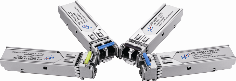
- SFP Fiber Transceiver(39)
- 10G SFP Transceiver(54)
- QSFP Optical Transceiver(26)
- Fiber Ethernet Switch(18)
- Industrial Ethernet Switch(26)
- Industrial POE Switch(27)
- Fiber Optic Accessories(17)
- About Us
- Quality Control
- Contact Us
- Get Quotations